Too lazy to read? click here for the TL;DR
OSI Model: Standardizing to Communicate
After a hiatus of almost a month without new posts here on the blog, I’m back. I hope during this time you’ve been thinking and reflecting on your “wanderings” as you navigate the cyber field.
By now, you already know that the project’s name is a playful reference to the human being as layer 8 of the OSI model. So we’ll start from the premise that we already know the 8th layer — even though it doesn’t officially exist. Therefore, the moment has come to dive deeper into the OSI model in a playful and understandable way for everyone. So, let’s go!
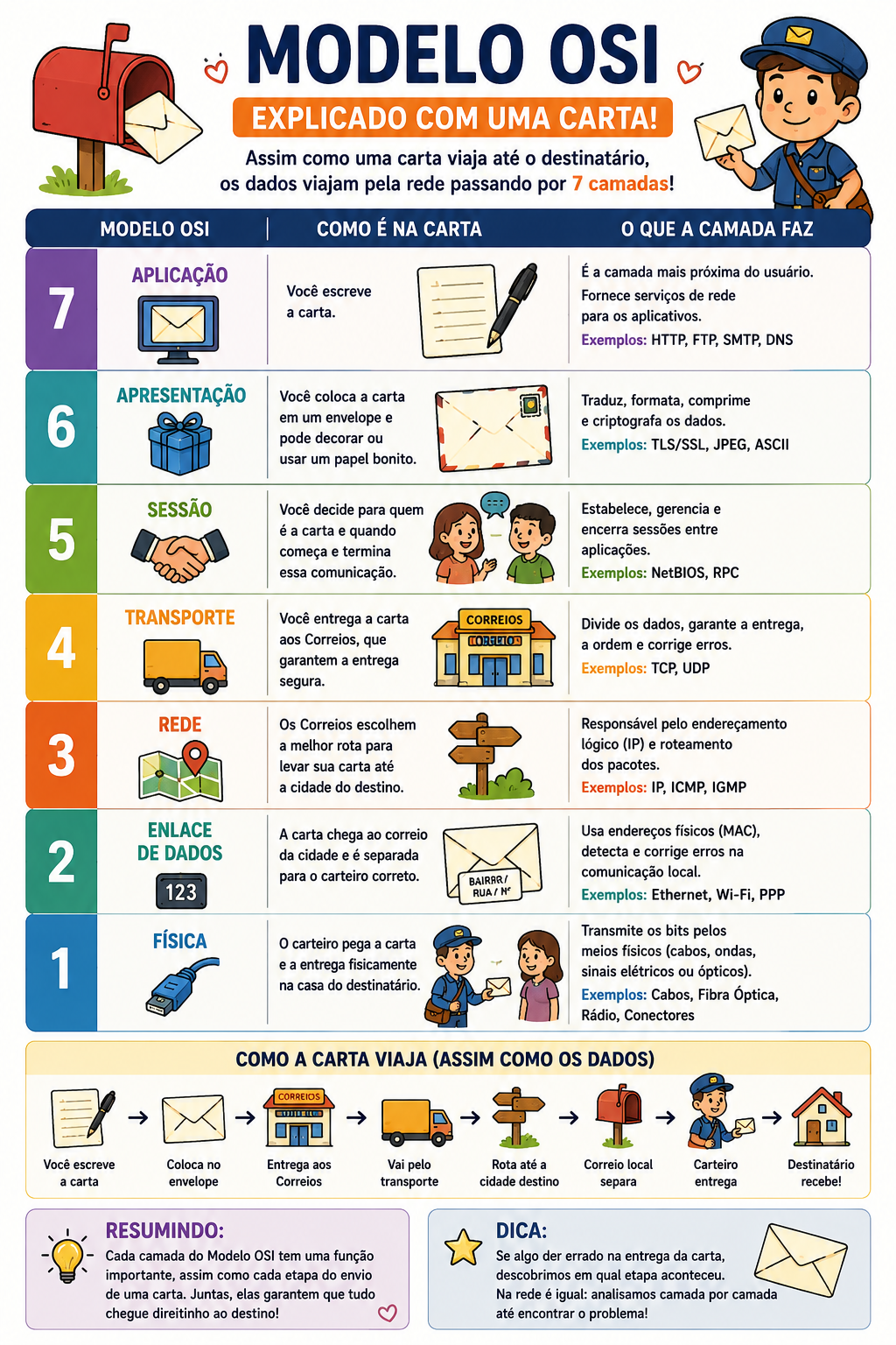
To explain this content, I could use several examples, like building a house or manufacturing and delivering a car, but I believe that using the writing of a letter and its delivery to the recipient as an example is the easiest way to understand this standard. History
In the early days of computing, each manufacturer had its own way of communicating. Now, let’s draw a parallel with sending letters. What was happening was as if each person invented their own way of communicating. If another person tried to read the letter, they wouldn’t understand it. Only each writer’s own “family” could understand. Maybe not even that. Bringing it to today, it’s as if computer manufacturers like Dell, Lenovo, Vaio, and Acer couldn’t communicate with each other. Or if phones made by Apple, Samsung, Motorola, and Nokia couldn’t talk to each other. It would be chaos.
Back then, proprietary networks like IBM’s SNA (1974), Digital Equipment Corporation’s DECnet (1975), and Xerox’s XNS (the basis for Ethernet in 1972) dominated, but they prevented connections with other manufacturers.
Faced with this, the Open Systems Interconnection (OSI) Model was created by the International Organization for Standardization (ISO) with the goal of standardizing communication between computer networks, solving incompatibilities between the proprietary systems of the time. And that lasts to this day. It was developed in the late 1970s, more precisely in 1977, and published in 1984 as ISO 7498. Building the OSI Model
As we saw, the construction of the OSI Model had to achieve a few goals:
- standardize networks;
- facilitate communication;
- allow different devices to talk to each other; and
- simplify maintenance.
Given this, the OSI Model was structured into 7 layers, which are:
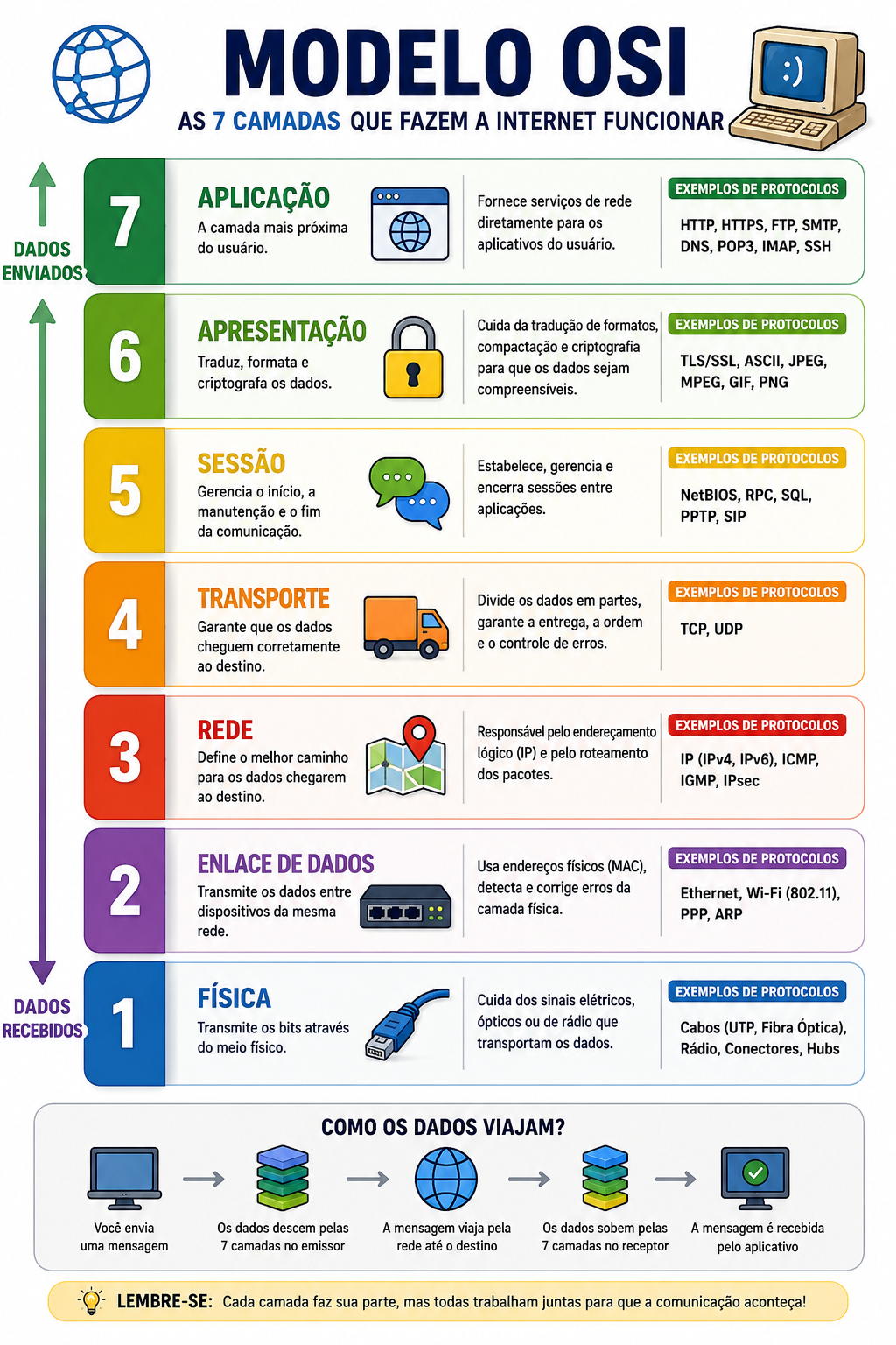
Now, an image of the OSI Model using our letter-sending example:
Understanding the layers
Layer 7: Application
The application layer is the only one you actually “see” and use every day: WhatsApp, email, Facebook, Instagram, among others. In a letter, it’s the content of the letter.
Layer 6: Presentation
This is the layer that translates languages. When writing the letter, no matter the language, whoever reads it will have the content translated into their own language. Also, the letter has been sealed with a secret code or a stamp so nobody peeks at the content. That’s what the presentation layer does: it translates, compresses, and encrypts data.
Layer 5: Session
This layer controls the start, maintenance, and termination of communication. It ensures that two devices know when to start and stop “talking.”
Layer 4: Transport
Here data begins to be divided into smaller parts. For curiosity’s sake, data starts being split into 1,500-byte packets. This is called MTU (Maximum Transmission Unit) and refers to the packet size. The transport layer guarantees correct delivery, the order of information, and error control. Here, the most famous protocols are TCP and UDP. It’s worth going a little deeper here. These two protocols are completely opposite: one seeks certainty that the recipient receives all packets (TCP) while the other prioritizes delivery over quality (UDP).
Transmission Control Protocol (TCP): it’s the careful one. It checks if everything arrived, if something is missing, and if resending is necessary. It’s like sending important documents via the post office with a delivery confirmation receipt. It’s used in chat applications like WhatsApp, Telegram, Facebook, and Instagram, among others.
User Datagram Protocol (UDP): it’s fast, but less careful. It’s used in live streaming, online games, and video calls. When you’re watching that football or baseball game, this is the protocol used so the transmission happens without hiccups.
Layer 3: Network
Where should the data go? That question is answered at this layer. If your letter needs to leave Brazil heading to the USA, Israel, or Japan, the routing will happen at this layer. In our analogy, this is the moment the distribution center looks at the ZIP code or address, checks the maps, and decides the best route. This is called IP addressing. It’s like a GPS choosing the fastest route between cities. This layer works with routers, IP addresses, and path selection.
Layer 2: Data Link
If the network layer is the GPS that finds the cities, the Data Link layer is the one that knows the city in detail, locating every street and every neighborhood. It’s the local mail carrier. This layer organizes communication within the local network. It controls network cards, MAC Addresses (we’ll understand what that is later when we study computer parts, but for now, understand it as the unique address of a network card), and switches. By analogy, the IP address here is like the building or city address, and the MAC Address is like the apartment or house number.
Layer 1: Physical
This is the material world. Here we have what actually transports the signals: cables, connectors, Wi-Fi waves, and fiber optics. This layer sends only electrical, light, or radio wave signals. In short: the physical layer is the infrastructure. In our letter-writing-and-sending analogy, this layer is equivalent to the paper and pen. If the paper is wet or the pen fails, communication doesn’t even start.
And now: is the OSI Model the only one in the world?
The answer is: no. Although the OSI Model is extremely famous, it’s not the only existing model. In practice, the modern internet mainly uses another model called the TCP/IP Model.
So, we can understand that the OSI Model is the ideal plan of how communication should work, and the TCP/IP Model is how it really works in practice.
This TCP/IP Model can also be called the Internet Model or the DoD Model (the TCP/IP model was born from an American military project, DARPANET, in the 1970s, even before the OSI Model).
See the image below for a comparison between the OSI Model and the TCP/IP Model:
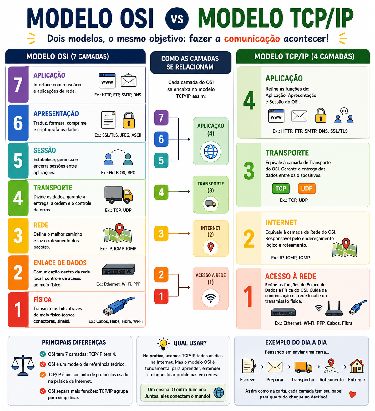
Even though there are several other models beyond OSI and TCP/IP, such as IBM SNA, Novell IPX/SPX, AppleTalk, and DECnet, there isn’t one model better than another. Their purposes are different. Remember: the OSI Model is a reference model, used for studying, teaching, diagnosing problems, and designing systems, while the TCP/IP Model is the model that actually runs the internet. It wasn’t created to be didactic. On the contrary, it was created to work. And it achieved its goal so well that it became the foundation of the entire modern internet.
Conclusion
After such a long read, I hope that from today onward you can pause every time you use a device and reflect: what kind of communication is happening here? Which layer? What would it look like in the OSI Model? And in the TCP/IP Model?
The main point I want you to take away after reading this post is: you don’t need to be a hacker or a tech expert to understand. Everything is achievable. And that’s the goal of this project. With each post, we’ll learn a little more. See you in the next post. Until next time!